|
|
|
|||
|
GalleryPegasus FELBecause the radiation wavelength of 13 microns is only one order of magnitude smaller than the beam size, diffraction is the dominating effect within the FEL. During start-up of the FEL the higher modes escape transversely out of the electron bunch and do not contribute to the amplification. The first animation shows this process as well the self-organizing of the radiation field towards rotational symmetry (transverse coherence) within the first half of the undulator. During the remaining FEL action the shape of the radiation field remains almost unchanged and only the amplitude grows (not visible in the movie, because the field amplitude has been normalized for each image) as well as the slow motion of the field in the forward direction, which is caused by the slippage effect. The second movie shows a 360 degree fly-around of the radiaiton field in the start-up regime
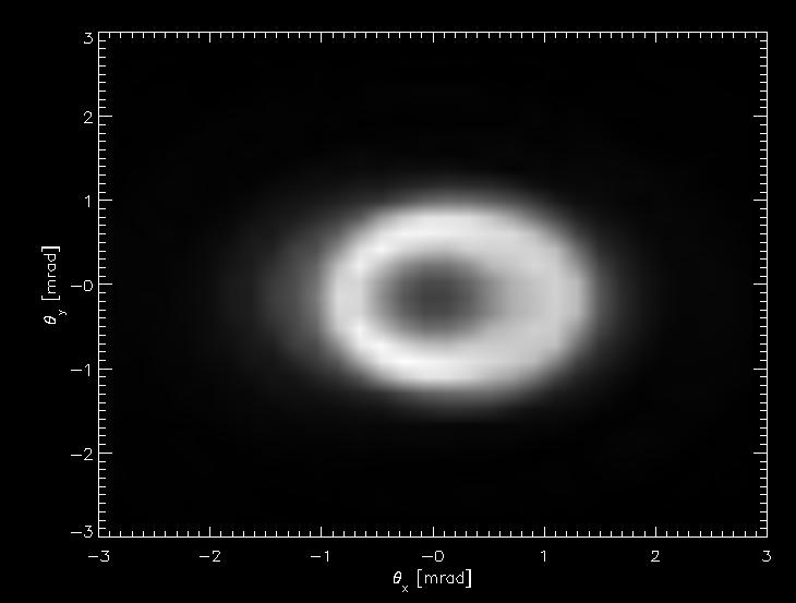
VISA FELThe VISA FEL required a very detailed analysis with GENESIS 1.3. It wasn't sufficient to define current, length and emittance in the main input deck, because the beam transport to the undulator distorts the phase space distribution of the electron beam. After GENESIS 1.3 was extended to accept complete phase space distribution, the start-end simulations yield the correct FEL performance including saturation and a hollow angular distribution. In addition the simulation, starting from the gun and propagation the modelled beam till the end of the undulator, aggres with other measurement, not related to the FEL.
The VISA is currently going into its second stage. A bunch compressor shortens the driving electron bunch, while a better beam transport avoids the strong distortion of the phase space distribution. Below is the simmulation of the FEL radiation evolution for the compressed electron bunch (Note: I am not responsible for the music choice)
TTF FELThis is TTF FEL operating at a wavelength of 110 nm. The two plots containing the radiation power and the bunching factor as a function along the undulator (z-axis) and position within the bunch (t-axis). The radiation profile has been normalized to unity to exclude the strong exponential growth, which would overshadow the details of field and bunching at the start-up regime. It is clearly visiable that the field starts with a lot of spikes. During the FEL interaction the number of spikes is reduced and their sizes get wider. The spikes have a characteristic slope, which is determined by slippage and amplification because the electron bunch acts as a dispersive medium. At the end of the undulator, the FEL reach saturation for the main spikes. The beam is then non-dispersive and the group velocity changes to the speed of light. The first animation illustrate this, which namely the longitudinal cut in the picture of the radiation field as it propagates through the undulator (in the plot from the bottom to the top).The second animation is a snapshot of the t-x plane around saturation over 4 radiation wavelength, when the microbunching becomes visible.
FEL AnimationThe following animation is not based on actual Genesis calculation but aimed to give an understanding of the FEL process. It has been used for the Expo 2000 at DESY/Hamburg. All copyrights are DESY.
|
|||||||||||||||||||||||||||||||||||||||||||||||||||||||||||||||||||||||||||||||||||||||||||||||||||||||